By Orias AI
AI Texture Generator: How to Create Seamless PBR Materials for 3D Models
AI texture generators can supply a tileable visual source, but 3D teams still need coordinated PBR maps, seam checks, lighting tests, and correct exports.
An AI texture generator produces a source image; a PBR material needs coordinated maps
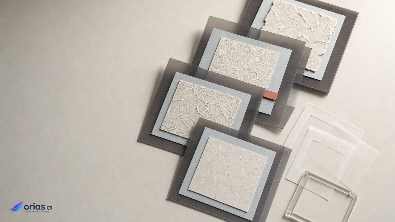
The useful mental model is simple: an AI-generated texture image is a source, not the finished 3D material. It can establish a surface’s color variation, marks, pattern, and broad character, and it may be prepared as a tileable visual source.
A PBR material instead describes separate properties through coordinated maps. Common outputs include base color or albedo, normal, roughness, metallic, height, ambient occlusion, opacity, and emissive, although the required set varies by renderer and delivery format. Adobe’s texture workflow overview describes these as distinct outputs rather than one pre-lit picture.
From the base concept, derive or refine the map set needed by the project: base color, roughness, metallic, normal, and height, with optional maps where appropriate. Then inspect the material on a lit 3D object and the final model, correcting seams, scale, UV distortion, map channels, color space, and implausible metalness or roughness. The material must respond plausibly under the project’s lights, camera angles, and renderer, not merely look convincing in a square preview.
Renderer requirements can change the available outputs and the format expected at export, so conversion or remapping may be required. Adobe’s PBR guide notes the same renderer-dependent constraint.
Define the surface and delivery target
Before generating a material, define its substrate, finish, wear level, intended viewing distance, physical scale, and whether it must repeat across a small prop or a large architectural surface. “Old painted wall” leaves too much unresolved; “matte off-white painted plaster with sparse hairline cracks and no directional grime, intended to repeat at wall scale” gives the texture process useful boundaries. Establish the intended repeat size and use it consistently in the material and on the model: a scratch pattern that reads convincingly on a phone case can appear implausibly large when repeated on a vehicle panel.
Choose the delivery endpoint at the same time. A renderer-specific material, a game-engine import, or glTF changes the required outputs, map handling, and channel packing. The production sequence is to define the material and scale, generate a tileable base concept, create or estimate companion maps, inspect and correct the result, and export it for the target renderer. Record map names, resolution, repeat scale, the receiving pipeline’s normal-map convention when applicable, color-space expectations, and the final file format in a handoff specification. Khronos’ glTF PBR documentation provides a reference for the relevant material model.
Make the base texture tile at its borders
A seamless texture matches at opposing image edges so that repeated copies do not reveal a grid. Tileability is not merely a nice preview option. It is a central constraint alongside visual realism and memory efficiency in research on seamless texture synthesis. SeamlessGAN research, for example, frames repeatable boundaries and controlled memory use as core problems.
Generate or process with repetition in mind, then test the actual edges. In an offset or tiled view, look for broken veins, cut bricks, abruptly ending fibers, a color jump, and features that form an obvious cross at every repeat. A texture can look excellent as one flat square and fail immediately when placed in a 3-by-3 grid.
- View several repeats horizontally and vertically, not just one duplicate.
- Check both the base-color pattern and the high-contrast details that the eye will track first.
- Remove or redistribute unusually distinctive marks if they make the repeat easy to spot.
- Choose resolution according to the asset’s screen use and texture budget; raising resolution does not repair a bad boundary.
For directional materials, decide whether direction is a feature or a liability. Wood grain, brushed finishes, and woven structures may need alignment to model UVs. Randomized orientation can conceal repetition for some materials, but it can also destroy a directional surface logic. The right choice comes from the model and shot, not from the source image alone.
Build coordinated PBR maps
Each map should describe the same surface from a different operational angle. Base color carries the material’s inherent visible color and pattern; it should not be used as a catch-all for strong lighting cues that belong to the scene. Roughness controls whether reflections are sharp or blurred. Metallic identifies whether the surface behaves as metal or dielectric. In the glTF metallic-roughness workflow, those are separate properties with separate visual consequences. Khronos’ PBR guidance defines metallic in those terms and explains roughness as the control on reflection sharpness.
Normal maps simulate small changes in surface direction without adding equivalent geometric complexity. They can make pores, fine grain, embossing, or shallow scratches catch light, but they do not create silhouette-changing geometry. Height maps provide scalar relief information that a pipeline may use for displacement or other effects; whether that becomes visible geometric relief depends on the renderer and material setup. Do not assume a normal map alone will make a deep crack alter an object’s outline.
The practical test is correspondence. If the base-color image shows chipped paint exposing metal, the roughness and metallic maps need to support that story rather than applying a uniform response everywhere. An attractive source image cannot reliably settle those values by appearance alone: dark material is not necessarily metal, and a bright highlight baked into an image is not proof of a glossy surface.
| Map | What to review |
|---|---|
| Base color | Color, pattern, and the absence of lighting that locks the texture to one scene. |
| Roughness | Whether reflected highlights have the appropriate sharpness or blur across the surface. |
| Metallic | Whether regions are intended to behave as metal or dielectric, rather than simply looking dark or bright. |
| Normal and height | Whether fine directional detail agrees with the visual pattern and remains appropriate for the model scale. |
Ambient occlusion, opacity, and emissive maps are optional additions, not automatic requirements. Include them when the material and target support a real use: occlusion for the intended shading workflow, opacity for cutouts or transparency, and emissive for self-illuminated regions. Extra maps without a delivery purpose increase review and integration work.
Validate on a sphere and the final UV-mapped model
Start validation on a lit sphere or similarly simple form. It exposes broad reflection behavior, normal intensity, and tiling more clearly than a busy production asset. Move the light or inspect under more than one lighting condition so that roughness and normal detail cannot hide behind a single flattering setup.
Then apply the material to the final UV-mapped model. This is where texture scale, UV stretching, island boundaries, and orientation become visible. Check the areas closest to camera, high-curvature sections, seams, and places where a repeated pattern crosses from one UV island to another. A sphere is a diagnostic surface, not a substitute for the final asset.
AI-assisted texture generation adds another reason to inspect from multiple angles. Text-guided 3D texture research identifies view inconsistency, seams, and Janus-like artifacts as recurring problems, and its mitigation methods include multi-view generation, inpainting, and iterative projection. Research on WonderTex supports the practical rule: do not approve a material from one preview angle.
A useful review sequence is simple: tile the source image; inspect it on a lit sphere; apply it to the model; rotate through relevant views; then correct the first fault that changes the material read. That may be a border seam, stretched scale, a channel assignment error, or physically implausible metallic or roughness values. Re-run the test after each meaningful correction rather than trying to judge several changes at once.
Pack and color-manage maps for delivery
Export is a material-quality step: prepare maps according to the receiving renderer’s requirements for naming, connections, conversion, packing, and output. For glTF’s metallic-roughness workflow, a combined texture supplies roughness from the green channel and metallic from the blue channel; those values use a linear transfer function. Incorrect color management can therefore produce incorrect material response. The glTF 2.0 specification documents the channel convention and linear handling.
Before handoff, open the exported material in the target environment for a short lighting test. Verify the intended treatment of base color and data maps, the expected inputs for packed channels, and the material read at the intended texture scale. Deliver the validated material in the format the next team can use, rather than only an AI image or a folder of maps.
Frequently Asked Questions
Can an AI texture generator make a seamless texture?
It can provide a tileable candidate, but seamlessness should be verified by repeating the image across both axes. Border mismatches and conspicuous repeated marks may still require correction.
Which PBR maps do I need?
Base color, roughness, metallic, normal, and height are a practical core map set. Ambient occlusion, opacity, and emissive are added when the material and target renderer have a defined use for them.
Should dark regions in the source image be metallic?
No. Metallic describes whether the surface behaves as metal or dielectric; image brightness alone does not establish that property. Review the intended substrate and its response under lighting.
Does a normal map add geometry?
A normal map simulates small directional surface changes without equivalent geometric complexity. It can improve fine lighting detail, but it does not provide the silhouette change associated with actual geometry.
Why test the material on the final model?
The final model reveals UV distortion, texture scale problems, island seams, and angle-dependent artifacts that a flat image or sphere cannot show. Review it from several relevant views before export.